Description
No. |
Description |
Qty. |
Removal notes |
Installation notes |
Details |
|---|---|---|---|---|---|
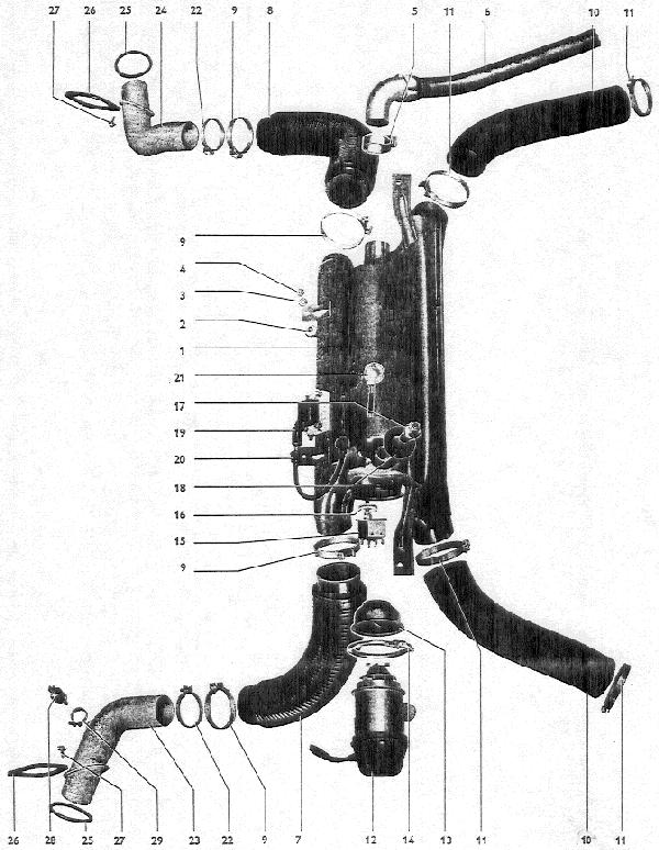
1 |
Casing and heat exchanger |
1 |
Remove coil spring and shock absorber on left hand side of axle |
Check casing for corrosion and heat exchanger for combustion deposits |
|
2 |
Bonded rubber mounting |
4 |
Check bolts for tightness in rubber mountings |
||
3 |
Lock washer B6 |
4 |
|||
4 |
Hexagon nut M6 |
4 |
|||
5 |
Clamp for exhaust pipe |
1 |
|||
6 |
Exhaust pipe |
1 |
Check for corrosion and deposits |
Ensure free movement |
|
7 |
Warm air hose, left (heater to vehicle interior) |
1 |
Check for leaks |
Ensure tightness of clamps and good seating |
|
8 |
Warm air hose, right (heater to vehicle interior) |
1 |
Check for leaks |
Must not touch exhaust pipe, ensure good sealing |
|
9 |
Clamp for warm air hose |
4 |
Ensure clamp is tight |
||
10 |
Warm air hose (heat exchangers to heater) |
2 |
Check for leaks |
Right hose must not touch exhaust pipe, ensure good sealing |
|
11 |
Clamp for warm air hose |
4 |
Ensure clamp is tight |
||
12 |
Combustion air blower |
1 |
Check blower fan and vanes for wear and ensure parts are tightly installed |
||
13 |
Housing with vanes |
1 |
Groove must engage in projection in heat exchanger |
||
14 |
Clamp for blower |
1 |
|||
15 |
Thermo switch with union nut |
1 |
If necessary, use solvent to loosen |
Do not bend sensor tube, adjust gap between switch location and union nut (0.31”/8 mm) |
|
16 |
Thermo switch seal |
1 |
Replace damaged seat |
Ensure proper sealing |
|
17 |
Glow-spark plug |
1 |
Box wrench 22 mm A/F |
Clean and check operation |
|
18 |
Plug bush seal |
1 |
Replace damaged seal |
Ensure proper sealing |
|
19 |
Ignition coil |
1 |
|||
20 |
Ignition cable |
1 |
|||
21 |
Overheating switch and cable harness |
1 |
If damaged, replace complete |
Test overheating switch for continuity |
|
22 |
Clamp for warm air pipe |
2 |
|||
23 |
Warm air pipe, left, with adapter for temperature sensor |
1 |
Ensure firm connection and good sealing between adapter and temperature sensor |
||
24 |
Warm air pipe, right |
1 |
Ensure firm connection |
||
25 |
Seal for warm air pipe |
2 |
Replace damaged seal with new one |
||
26 |
Flange for warm air pipe |
2 |
Left and right flange are symmetrically opposite |
||
27 |
Hexagon head bolt and washer for flange |
4 |
|||
28 |
Temperature sensor |
1 |
|||
29 |
Clamp for temperature sensor |
1 |