Ribbed heat exchanger and other changes (CA only)
In order to insure that the heater output meets the requirements of extreme climactic zones the heater system has been changed.
The engine heat exchangers are finned
The hot air fan has a two stage switch:
First stage (current draw 70 Watt)
Second stage (current draw 160 Watt)
The two stage switch for the fan operates automatically. The first stage is limited to stationary heating operation. The second stage is automatically switched on when the engine is started (voltage at regulator swicth D+). This ensures that the current draw is limited during stationary operation.
Service installation into previously produced vehicles is not intended.
Wiring diagram
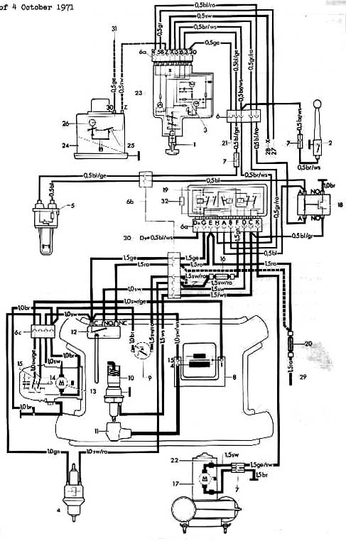
Cable colors
ro: red
bl: blue
sw: black
br: brown
ge: yellow
ws: white
gn: green
Legend
Warning lamp
Main switch
Electronic switch
Fuel pump
Temperature sensor
Plug housing
6a. Multi point plug (Temperature switch, relay)
6b. Plug housing (VW 411 wagon)
6c. Plug housing of the combustion air blower cable harness
Cable connector
Ignition coil
Overheating switch
Glow/Spark plug
Angled plug with ignition cable
Thermo switch
Combustion air fan motor
Contact breaker for pump
Contact breaker for ignition
Overheating fuse 8 amp.
Hot air motor
Safety switch
Double relay
Fuse 16 amp.
To terminal 30 of safety switch
Suppression choke
Temperature regulating switch
Time switch
Operational readiness switch
Clock contact
To parking light
To ignition/starter lock
To starter (terminal 30)
To regulator switch
To lighting switch (terminal 30)
Series resistance for hot air fan
The cable which is shown dotted - from the 16 amp. fuse (20) to the plug housing (6b) - belongs to the VW 411 wagon.