Description
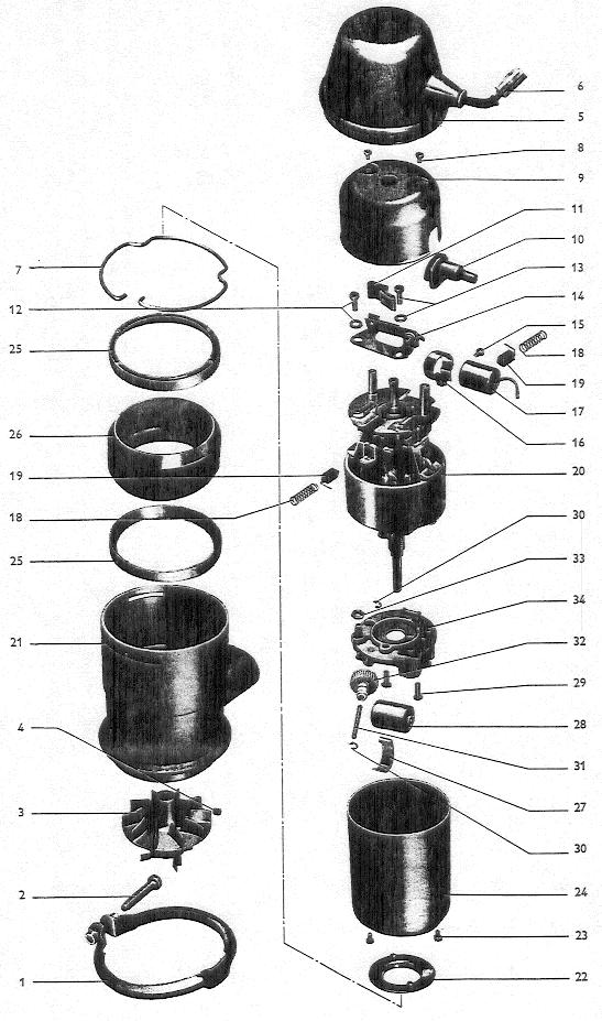
No. |
Description |
Qty. |
Removal notes |
Installation notes |
Details |
|---|---|---|---|---|---|
1 |
Combustion air blower clamp |
1 |
|||
2 |
Fillister head screw |
1 |
|||
3 |
Blower fan with vanes |
1 |
Adjust gap between blower fan and motor support housing to 0.039” (1 mm). Push carefully onto shaft (excessive pressure causes damage). Pressure must not exceed 500 grams (18 ounces). |
||
4 |
Socket head capscrew |
1 |
Back off with 2 mm Allen wrench |
Screw against flat on shaft, seal with Loctite |
|
5 |
Cap for motor |
1 |
Replace if damaged |
Ensure proper sealing, fits over tensioning ring |
|
6 |
Cable harness and plug |
1 |
Note colors when unsoldering |
note markings in plug |
|
7 |
Tensioning ring |
1 |
Expand slightly, otherwise tension will be lost |
Press taper ring (25) far enough into motor support so that spring can be easily installed |
|
8 |
Fillister head screw |
2 |
Seal with paint |
||
9 |
Cap |
1 |
|||
10 |
Rubber grommet |
1 |
|||
11 |
Lubricating felt |
1 |
Lubricate felt with lithium grease |
||
12 |
Screw and washer |
1 |
After installing, seal with paint |
||
13 |
Locking screw and washer |
1 |
After installing, seal with paint |
||
14 |
Contact breaker for ignition |
1 |
Check for erosion and check gap |
Adjust gap to 0.016” (0.4 mm), no grease on points! |
|
15 |
Fillister head screw |
1 |
|||
16 |
Condenser clamp |
1 |
Ensure good ground connection |
||
17 |
Condenser |
1 |
Test |
||
18 |
Brush spring |
2 |
|||
19 |
Carbon brushes |
2 |
Check for wear |
Note pigtail guide |
|
20 |
Pole housing, armature and brush holder |
1 |
Check for commutator erosion and bearing damage |
Axial play of armature max. 0.012” (0.3 mm). Motor shaft must not be loaded in axial direction more than 500 grams (18 ounces) |
|
21 |
Motor support housing |
1 |
Clean, if damaged install new one |
||
22 |
Rubber support ring |
1 |
Replace if damaged |
Rubber ribs must engage in holes of motor housing |
|
23 |
Cheese head screw |
2 |
|||
24 |
Motor housing |
1 |
|||
25 |
Taper ring for motor support |
2 |
Push one taper ring, with its flat surface first, into motor support housing as far as it will go |
||
26 |
Motor support rubber ring |
1 |
Insert rubber ring and taper ring into motor housing |
||
27 |
Condenser clamp |
1 |
|||
28 |
Condenser |
1 |
Test |
||
29 |
Countersunk head screws for contact breaker plate |
2 |
Seal with paint |
||
30 |
Circlip |
2 |
|||
31 |
Gear shaft |
1 |
|||
32 |
Gear |
1 |
|||
33 |
Locknut |
1 |
|||
34 |
Contact breaker plate with contact for fuel pump |
1 |
Check points for erosion, check gap |
Adjust breaker point gap (0.016”/0.4 mm) |