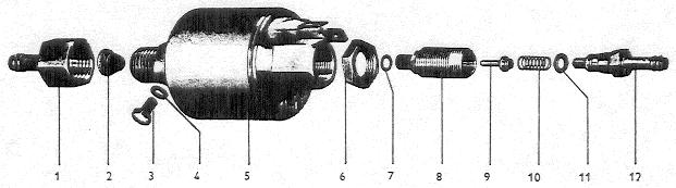
“Andres” Pump
No. |
Description |
Qty. |
Removal notes |
Installation notes |
Details |
|---|---|---|---|---|---|
1 |
Connection |
1 |
Hold at pump housing with 15 mm open-end wrench |
||
2 |
Strainer |
1 |
Clean |
||
3 |
Bleeder screw |
1 |
|||
4 |
Special ring seal |
1 |
Adhesive side to pump housing |
||
5 |
Pump housing |
1 |
Test winding for continuity, clean housing |
||
6 |
Lock nut |
1 |
After adjusting seal with paint |
||
7 |
O-Ring (4x1 mm) |
1 |
Check for damage |
Moisten with filtered gasoline, replace if damaged |
|
8 9 10 |
Valve body Control valve Spring |
1 |
Clean in acetone. If one part is damaged install complete new fuel check valve and readjust |
Chapter 1.3 and this page |
|
11 |
O-Ring (4x1.5 mm) |
1 |
Moisten with filtered gasoline, replace if damaged |
||
12 |
Valve connection |
1 |
Clean in acetone, counterhold at valve body with 10 mm open end wrench |
Installing and pre-adjusting fuel check valve
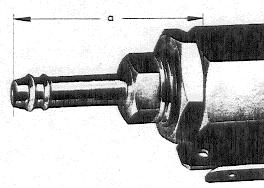
Screw lock nut onto fuel check valve.
Screw fuel check valve into pump housing until there is a gap “a” of 1.18” (30 mm) between valve connection and pump housing.
After assembling, adjust pump accurately on measuring device (see Chapter 1.3).