Wiring Diagram
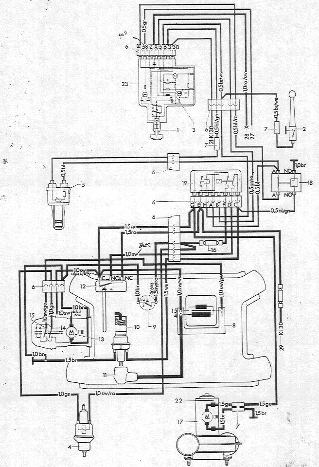
Warning Lamp
Main switch
Electronic component
Fuel pump
Temperature sensor
Push-on terminal
Cable connector
Ignition coil
Overheating switch
Glow-spark plug
Angled connector and cable
Thermo switch
Combustion air blower
Contact breaker for pump
Contact breaker for ignition
Overheating fuse (8 Amps)
Heater air blower
Safety switch
Dual relay
n/a
to terminal 30 in fuse box
End choke 4-H
Temperature regulating switch
n/a
n/a
n/a
to parking light
to starter-ignition switch
to starter, terminal 30
Explanation (Heater with time switch)
The clockwork mechanism is wound up by pressing the temperature regulating switch (23) in and turning it to the right to the stop. The main switch contact (2) must be closed and the heater is then switched on.
Current flows from the fuse box terminal 30 to contact 30 in the temperature regulating switch (23) and passes via the switch to the warning lamp and to terminal 4 of the switch (23). This means that the current also reaches contact A on the relay (19) via terminals A-A of the safety switch (18).
When heater is first switched on, the temperature sensor (5) is surrounded by cold air, so that its resistance is high. The setting regulator of the temperature regulating switch is set to a relatively high flow temperature. The electronic component (3) switches the heater on by grounding terminal 5 of the switch (23) via the outlet transistor.
Terminal 5 of the thermo switch (12) is connected to terminal B of the dual relay (19) so that the relay is energized.
When the heater has reached the desired temperature, the switch (23) turns the dual relay off via terminal B. The current to the fuel pump is cut off and the heater stops burning until the temperature sensor reports “too cold” and the fuel supply is switched on again.
When the relay is energized, the heater and combustion air blowers (17 and 13) start working. The current flows from terminal 30 on the starter through the connector (21) and terminals E-G of the dual relay to the heater air blower. Current also flows from terminal G of the relay via terminal C of the thermo switch (12) to the combustion air blower.
The electric fuel pump (4) is provided with voltage via the relay contact E-F and via the short circuit fuse (16) and begins to pump fuel into the combustion chamber controlled by contact breaker 14 in the combustion air blower. The glow element in the glow-spark plug (10) is switched on via dual relay contact E-G, thermo switch contact C-NO and dual relay contact D-C. The element heats up and pre-heats the air/fuel mixture being delivered to the combustion chamber by the combustion air blower.
At the same time the glow-spark plug is energized, the ignition coil (8) also cuts in. The contact breaker (15) then breaks the primary circuit, as on the vehicle engine. The high tension of about 5000 Volts induced in the secondary winding by this means passes to the glow-spark plug via an ignition cable with angled connector (11) and ignites the air/fuel mixture.
When the flame has heated the feeler tube of the thermo switch sufficiently, contact C-NO of the thermo switch opens and switches the glow-element off. The ignition system, however, continues to function.
When the temperature regulating switch goes off, the heater and combustion air blowers continue to run and receive current via relay terminals E-G because the relay winding A-H is still energized. The ignition system also continues to receive current.
The heater air and combustion air blowers receive current via thermo switch contact NC-C and continue to run until the heater has cooled down and all traces of exhaust gas have been blown out. (The contact in the thermo switch is then in position C-NO again.)
The heater remains ready for action until the timer in the temperature regulating switch has run down (about 10 minutes) and the contacts have moved from position 30-4 to position X-4.
Note
If the ignition is switched on before the contact has moved to position 15-A, the heater can be switched off by turning the knob of the switch fully to the left.
The heater can also be switched off by cutting off the retaining current for the dual relay via the contact on lever 2.