Parts
Housing and heat exchanger
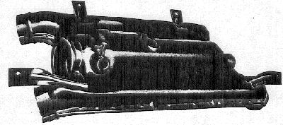
The flat, large heat exchanger is made of special sheet metal and is surrounded by two riveted cases of corrosion-proof sheet steel. The front cylindrical part of the heat exchanger, the combustion chamber, contains the housing with vanes and the combustion air blower. In addition, a glow/spark plug, a thermo switch, an ignition coil and an overheating switch are fitted to the heater.
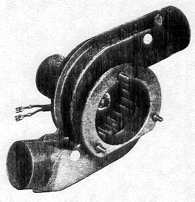
Combustion air blower
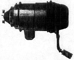
The combustion air is drawn in through an intake on the engine fan housing and transferred to the combustion chamber by a blower fan. The electrical impulses for the ignition and for the fuel pump are provided by two contact breakers mounted separately on the motor shaft.
The combustion air blower motors are made by Bosch and AEG. The pole housing of the AEG motor is painted black and the breaker contacts for the fuel pump and ignition are different. The complete motors can be interchanged.
Glow-spark plug
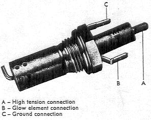
The glow-spark plug is comprised of a glow element and a spark plug with central electrode, contained in one unit. The plug protrudes into the combustion chamber. The cable from the ignition coil is connected to the glow-spark plug by a spark plug connector and a flat terminal is used for the glow element connection. The glow element operates for only a brief period when the heater is switched on, whereas the spark plug operates the entire time.
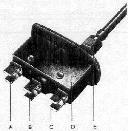
Ignition coil
High tension connection
Terminal 15
Terminal 1
The ignition coil is secured to the heater casing. The primary and secondary windings are in a cast plastic housing on one arm of the iron core. A plate protects the coil from excessive heat. The coil remains on the entire time the heater is operating. The primary winding receives impulses from the contact breaker on the combustion air blower shaft and induces in the secondary winding a high tension ignition voltage which is passed on to the glow-spark plug via an ignition cable.
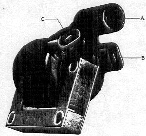
Thermo switch
Permanent positive connection
Glow-spark plug and safety switch connection
Intermittent positive connection
Switch housing
Union nut
The thermo switch is secured to a screw connection on the heat exchanger by a union nut. The sensor tube of the thermo switch protrudes into the combustion chamber. The thermo switch controls the length of time the glow element and the safety switch resistance operate and also the heater run-on time.
Overheating switch
The overheating switch is installed on the outer casing. It cuts off the current to the fuel pump via a fuse should a defect occur that would cause overheating.
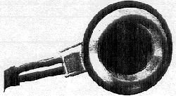
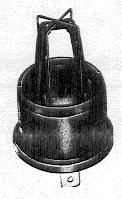
Heated air blower
The air blower is mounted near the engine cooling air intake. This blower forces air automatically, alternating with the engine cooling fan, through the two engine heat exchangers and the heat exchanger of the heater into the vehicle interior. If the engine cooling fan produces more air (high engine speeds), the non-return flaps in the electric blower close. If the electric blower produces more air (low engine speeds), the flaps in the engine cooling fan housing close automatically to prevent the air from escaping through the engine cooling air intake.
The heater air blower in the Type 4 wagon rotates in the opposite direction to the one on the Type 4 sedan and has a single outlet.
Current draw(installed): 8-9 amps at 13 volts.
Safety switch
This switch cuts off the current to the heater (dual relay opens circuit) if the combustion system should become defective (fuel supply cut off, glow-spark plug defective) within a time limit of max. 230 seconds after being actuated.
Switch response time: 150-230 seconds at room temperature and 12 Volts.
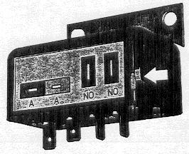
Electronic temperature regulating switch
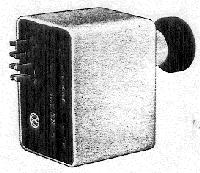
The switch is combined with the time switch and main heater switch in one housing. The warning lamp is in the switch knob.
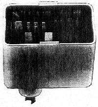
Temperature regulation is done with electronic curcuitry. Temperature-sensitive voltages are fed to the switch from a temperature sensor and the switch feeds two voltage conditions to the relay.
A main heater switch is incorporated.
It limits heater operation to 10 minutes when ignition is off.
Warning lamp to chassis No. 412 2064 917 (July 1972)
When the heater is switched on, the warning lamp in the knob of the temperature regulating switch lights up. When the parking lights or headlights are switched on as well, the intensity of the warning lamp is reduced by one half to reduce dazzle at night. This is done by an additional transistor in the temperature regulating switch via the cable on terminal 58 on the switch and the parking warning light (see wiring diagram).
Warning lamp from Chassis No. 413 2000 001 (August 1972)
The lamp in the knob of the heater switch is now wired as an illuminating light. The previous terminal 58 is now terminal 58b.
When the parking lights or headlights are switched on, the brightness of the warning light remains unchanged when the heater is turned on. It can be regulated along with the other instrument lights.
Regulating ranges
Upper range: 115-143 degrees centigrade (240-290 degrees Fahrenheit)
Lower range: 30-40 degrees centigrade (86-105 degrees Fahrenheit)
The switching points of the temperature regulating switch can only be roughly checked with electronic equipment.
Temperature sensor
The temperature sensor supplies temperature-sensitive voltage to the temperature regulating switch.
The temperature sensor has a temperature-sensitive resistance which has a high resistance value at low temperatures and a low resistance value at high temperatures.
Resistance: Measured in water at 60 degrees centigrade (140 degrees Fahrenheit) 3.5-5 kOhm
Fuel pump
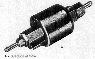
The amount of fuel delivered by the electromagnetic metering pump is directly dependent on the speed of the combustion air blower. At every 33rd revolution of the motor shaft, the pump receives an electrical impulse via the breaker contacts so that the fuel-air mixture is always constant ragardless of changes in the speed of the combustion air motor.
Delivery capacity: (To be measured at room temperature) 200 strokes = 11.8 to 12.5 cubic centimeters.