Current flow diagram
Current flow diagram after August 1972 (Chassis No. 413 2000 001)
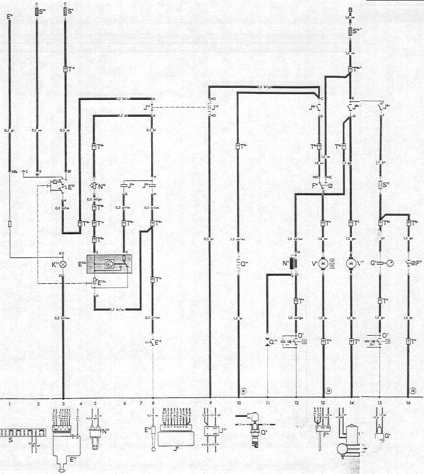
Symbol |
Description |
Track |
|---|---|---|
B |
Starter terminal 30 |
14 |
E 1a |
Light switch terminal 58b |
1 |
E 13 |
Temperature regulating switch (switching part) |
3 |
E 13a |
Temperature regulating switch (regulating part) |
5 |
E 13b |
Temperature regulating switch (electronic part) |
5, 6 |
E 16 |
Heater lever switch |
8 |
F 16 |
Flame switch |
13 |
F 17 |
Overheating switch |
16 |
G 6 |
Metering pump |
15 |
J 8 |
Relay |
6, 8, 13, 14, 15 |
J 10 |
Safety switch |
8, 9 |
K 11 |
Heater warning light |
3 |
N 10 |
Temperature sensor |
5 |
N 11 |
Ignition coil |
12 |
O 1 |
Contact breaker for ignition in combustion air blower |
12 |
O 2 |
Contact breaker for metering pump |
15 |
Q 5a |
Glow-spark plug (Glow element) |
10 |
Q 5b |
Glow-spark plug (Electrode) |
11 |
S 9 |
9th fuse in fuse box |
3 |
S 10 |
10th fuse in fuse box |
2 |
S 16 |
Main fuse (16 Amps; in fuse holder) |
14 |
S 17 |
Overheating fuse (8 Amps; in fuse holder) |
15 |
T 1a |
Wire connector, single (below rear seat bench) |
5 |
T 1b |
Wire connector, single (near frame tunnel) |
8 |
T 2 |
Wire connector, double (near heater blower) |
14 |
T 4 |
Wire connector on combustion air blower |
12, 13, 15, 16 |
T 8a |
Wire connector, eight connections (on dashboard, left) |
3, 4, 5, 6, 8 |
T 8b |
Wire connector, eight connections (in engine compartment, left, wagon) |
5, 10, 13, 14, 15, 16 |
V 4 |
Heater air blower |
14 |
V 6 |
Combustion air blower |
13 |
18 |
Ground strap on frame |
10, 13, 16 |
Wire color codes
ro = red
sw = black
ge = yellow
bl = blue
be = brown
ws = white
gn = green
gr = grey
Explanation
Switch heater on
Pull heater lever switch (E16) up until ground contact is closed.
Operate temperature regulating switch (E 13) to desired temperature
Start-up
The heater ignites within 60 seconds if the air drawn in is at room temperature. The start-up process is terminated by the flame switch (F 16).
Voltage can be measured at:
Terminal 30
Terminals A-A of safety switch (J 10)
Terminal A of relay (J 8a, J 8b).
Relay (J8) operates contacts E-G, E-F and C-D.
Terminals of fuse (S 16)
Terminals E-G of relay (J8)
The warm air motor (V 4) starts to work.
Terminal C of flame switch (F 16)
The combustion air blower motor (V 6) starts to work.
Terminal 15 of ignition coil (N 11)
No voltage or a low voltage can be measured at:
Heater lever switch (E 16)
Terminals 6-5 of temperature regulating switch (E 13b), ~3 Volts
Terminal B of relay (J 8a), ~3 Volts
Relay (J 8a) operates the contacts E-F and D-C.
Voltage can be measured at:
Terminal NO of flame switch (F 16)
Terminals D-C of relay (J 8a)
The glow element of the glow-spark plug (Q 5a) is energized. It warms the fuel/air-mixture to make it readily combustible. It is then ignited by the sparks from the glow-spark plug (Q 5a).
Terminals E-F of relay
Overheating fuse (S 17) 8 Amps
Terminal of metering pump (G 6)
The metering pump (G 6) starts to deliver fuel. At every 33rd revolution of the combustion air motor (V 6) the metering pump (G 6) receives an impulse via the contact breaker (O 6).
Heating
When the heater has ignited and warmed up, the flame switch (F 16) operates the contacts C-NC.
The following are de-energized:
Terminal NO of safety switch (J 10)
The glow element of the glow-spark plug (Q 5a)
The safety switch (J 10) does not operate.
Regulating
During regulation there are two voltages at terminal 5 of the temperature regulating switch (E 13b). These voltages are controlled by the temperature selection via the electronic circuitry (E 13b) and the temperature sensor (N 10). When the heater reaches the high heat output, the temperature sensor (N 10) records a high temperature and the temperature regulating switch (E 13b) indicates a high voltage at terminal 5 as the switching value for the relay (J 8a)
Voltage can be measured at:
Terminal 5 of the temperature regulating switch (E 13b)
Terminal B of relay (J 8a)
The relay now separates the contacts E-F and D-C.
The following are de-energized:
Contact of fuse in overheating switch (S 17)
Contact of metering pump (G 6)
The metering pump (G 6) stops delivering fuel and combustion stops. As the heater cools down and before the flame switch sensor tube can cool off sufficiently to close contacts C-N (less than 2 minutes), the temperature sensor (N 10) registers the lowered temperature and switches the heater back on.
No voltage or a low voltage can be measured at:
Terminal 5 of temperature regulating switch (E 13b), ~3 Volts
Terminal B of relay (J 8a), ~3 Volts
Relay (J 8a) reconnects the contacts E-F and D-C.
Voltage can be measured at:
Terminal F of relay (J 8a)
The metering pump (G 6) resumes fuel delivery.
Operation of overheating circuit
If the heater should overheat, the overheating switch (F 17) closes and causes a short circuit which blows the 8 Amp fuse (S 17).
This de-energizes:
Contact of metering pump (G 6)
The flame goes out and the run-on starts.
Operation of safety switch
The safety switch (J 10) responds when the flame switch (F 16) holds the contacts C-NO for longer than roughly two to four minutes because combustion has not taken place in the heater or because the thermoswitch (12) is defective.
Voltage can be measured at:
Terminals C-NO of flame switch (F 16)
Terminal NO of safety switch (J 10)
The following are de-energized:
Contact A of relay (J 8)
All connections in relay (J 8) are interrupted.
Contact C of flame switch (F 16)
The combustion air motor (V 8) stops. The ignition coil (N 11) is de-energized. The hot air blower (V 4) stops.
Contact F of relay (J 8)
The metering pump (G 6) stops delivering fuel.
Switching heater off
Turn knob of temperature regulating switch (E 13) back to the stop position. Press heater lever switch down to open ground contact (E 16).
The following are de-energized:
Contact A on relay (J 8)
All connections in relay (J 8) are interrrupted.
Run-on
The run-on lasts for about two minutes at an ambient temperature of 20 C (68 F) and is shorter at lower temperatures. The run-on is necessary in order to clear all traces of gas from the heat exchanger and cool it down. The flame switch limits the run-on period.
The following is de-energized:
Contact F of relay (J 8a)
The metering pump (G 6) stops working.
Voltage can be measured at:
Terminals N-C of flame switch
The combustion air motor (V 6) operates. The hot air blower (V 4) delivers air. When the heat exchanger has cooled down, the flame switch (F 16) operates contacts C-NO.
The following is de-energized:
Contact C of flame switch (F 16)
Hot air blower (V 4) and combustion air blower (V 6) are de-energized and the run-on is finished.