Operation
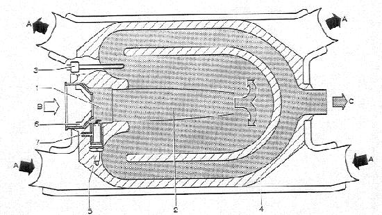
Combustion chamber
Heat Chamber
Thermo switch
Heat exchanger
Glow/spark plug
Housing with vanes
Fuel line connection
Warm air
Combustion air
Exhaust gases
Heating, engine off
All the heater functions are controlled by the heater flap lever in conjunction with the temperature regulating switch. The warning lamp in the switch knob lights up when the heating system is on.
Fuel is drawn through a T-piece in the vehicle engine fuel (return) line. It is forced through a filter and into the heater combustion chamber by a fuel pump. The air from the combustion air blower is swirled by a housing with vanes in front of the combustion chamber and the air and fuel then form a combustible mixture. The glow/spark plug, switched on at the same time as the fuel pump and the combustion air blower, ignites the air/fuel mixture. A flame is produced that heats the walls of the heat exchanger. The exhaust gases flow through an exhaust pipe to the atmosphere.
The temperature sensor in the left warm air duct, together with an electronic device and a setting regulator in the temperature regulating switch, keep the heater output temperature constant.
The air flowing from the heater air blower via the two engine heat exchangers and the open heater flaps passes through the heater. The heating chamber transfers its heat to the air passing through the heater booster. The hot air is then transferred through two hoses into the warm air ducts and to the outlets in the footwell and the instrument panel on both sides of the vehicle.
To switch the heating off, the heater flap lever is pushed forward until the warning lamp in the knob of the temperature regulating switch goes out. The heater air blower and the combustion air blower continue to run, however, until the heater cools down and all traces of exhaust gases have been purged from the combustion chamber (run-on)
Engine heating only, engine running
When the engine is running, exhaust gases on each side of the engine are led to the muffler through two pipes surrounded by sheet metal casings. Fresh air is continually blown through the sheet metal casings by the engine cooling fan and heated by the exhaust pipes. If the engine heat exchanger flaps are open, the heated air flows via the heater and the warm air ducts to the vehicle interior.
If the heater flap lever is pulled back fully, the heater air blower is switched on and the amount of air is increased. The warning lamp in the knob of the temperature regulating switch lights up.
Depending on the driving conditions, the larger amount of air is produced either by the engine cooling fan at high speed or by the electrically operated blower (city traffic).
Engine heating and heater booster, engine running
The air pre-heated in the engine heat exchangers flows around the heat exchanger of the heater booster and is heated further until the set temperature is reached. The heater air blower is always on at this point.
If the required temperature, regulated by the temperature control system, is attained, the heater booster is turned off automatically. When the temperature of the engine heating drops below the pre-set temperature, the heater booster automatically comes into operation again.