Component test instructions
To check the entire system for air leaks, disconnect one hose from the auxiliary air valve and blow compressed air through the hose with the throttle open. Soapy water on hoses and connections will then indicate leaks.
Location of components
Cold start valve, pressure regulator and air flow meter
Cold start valve
Pressure regulator
Air flow meter
Control unit and relays
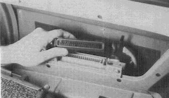
The control unit and relays in 412 models are behind the passenger side rear trim panel. The wiring harness plug is removed for many of the tests described in the Test Chart.
Fuel pump and fuel filter
The fuel pump and fuel filter are located under the vehicle front next to the gas tank (Bus shown in picture). The voltage check described in the Test Chart is performed at the plug contacts after the plug is removed.
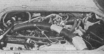
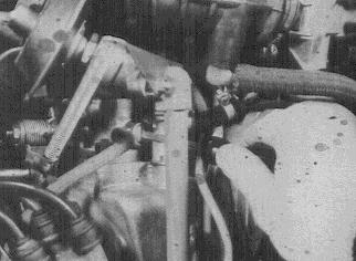
Fuel pressure

The fuel pressure test is made inside the engine compartment by removing the hose from the start valve and connecting pressure gauge KDEP 1034 in series with the line using a T-piece and extra length of hose as shown in the picture.
Before testing the system for correct pressure value, remove the pressure regulator vacuum hose at the regulator or manifold and block the opening (see Fuel System Description). Start the engine and let it idle. Read the gauge for the correct pressure: 2.2-2.6 bar. Now reconnect the vacuum hose to the regulator. The pressure should drop to about 2 bar at idle, and rise again when the throttle is opened. If this is not the case, check the vacuum hose for leaks.
A clean, unclogged filter is a prerequisite for accurate fuel pressure and delivery tests as described in the fuel pump test chart.
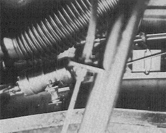
Auxiliary air valve
To test the auxiliary air valve, remove the 2 hoses from the valve and use a mirror and light source to look through the valve. It should be partially open when the engine is cold and fully closed when the engine is warmed up.
Thermo-time switch
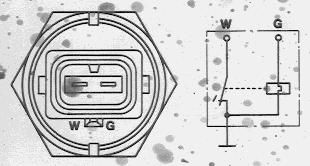
The thermo-time switch is tested in the vehicle for correct resistance values at certain engine temperatures as given in the Thermo-time switch test chart. For this purpose remove the plug from the switch and measure directly at the terminals of the switch. The illustration shows the condition of the thermo-time switch when the coolant temperature is below 50 F: Terminal W is connected to ground to complete the circuit and activate the cold start valve.
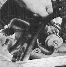
Air flow meter
The air flow meter is accessible after the air filter has been removed (Beetle shown in picture). Then the flap can be deflected by hand to test the pump safety contacts. The bypass air screw in the air flow meter (arrow) controls idle mixture. Turning the screw out (counterclockwise) reduces CO. See the Air flow meter test chart for correct values.
Idle speed
Idle speed on all VW vehicles is set with the large bypass screw in the throttle housing (Beetle shown in picture).
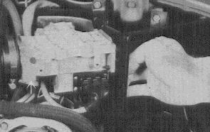
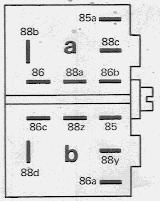
Double relay
L-Jetronic wiring harness
Vehicle wiring harness
To test the voltage supply to the injection valves, unscrew the double relay and turn it around so both terminal sets are accessible.
With the ignition on there should be full system voltage between terminal 88z and ground and between 88b and ground. If this is not the case, the relay is defective.
Also check the voltage at terminals 43/1 and 43/2 against ground to insure that the injection valves are being supplied with full system voltage. See the Electrical Wiring Diagram for terminal identifications.